
Nitrided Screw Surface Failure: How to Diagnose Cracking, Peeling, and Case-Layer Loss
Related news
Nitrided Screw Surface Failure: How to Diagnose Cracking, Peeling, and Case-Layer Loss


A nitrided screw can keep running after its surface has begun to fail, which is why early symptoms are easy to misread. A polished flight edge may be normal contact wear, while a dark patch may come from residue rather than damaged metal. Cracks, lifting flakes, or a rough surface that sheds particles require a different response because the hardened case may no longer be continuous.
The safest diagnosis combines location, operating history, dimensions, and laboratory evidence. Appearance alone cannot show damage depth or the barrel’s contribution. This process helps separate cosmetic change from active nitrided screw surface failure.
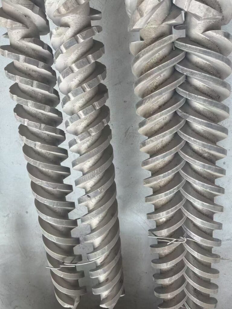
What Surface Failure Looks Like on a Nitrided Screw
Distinguish Normal Discoloration and Polishing From Cracks, Peeling, and Spalling
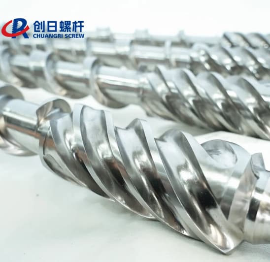
Normal service can leave smooth bright bands on flight lands, gradual color changes, or thin deposits that disappear during controlled cleaning. These marks usually follow predictable contact zones and do not create sharp edges. By contrast, nitrided layer peeling often shows raised margins, shallow flakes, or an irregular boundary between intact and exposed metal. White layer spalling may look like small brittle chips breaking from the outermost compound layer.
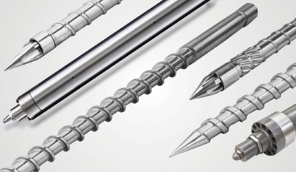
Cracks deserve immediate attention. Record whether they are longitudinal, circumferential, or branching, and whether they cross a flight root, land, or transition radius. A Nitrided Injection Molding Screw has several geometry changes where local stress and contact conditions differ, so the exact position matters more than a general statement that the surface is “damaged.”
Map Each Damage Pattern by Location and Operating Event
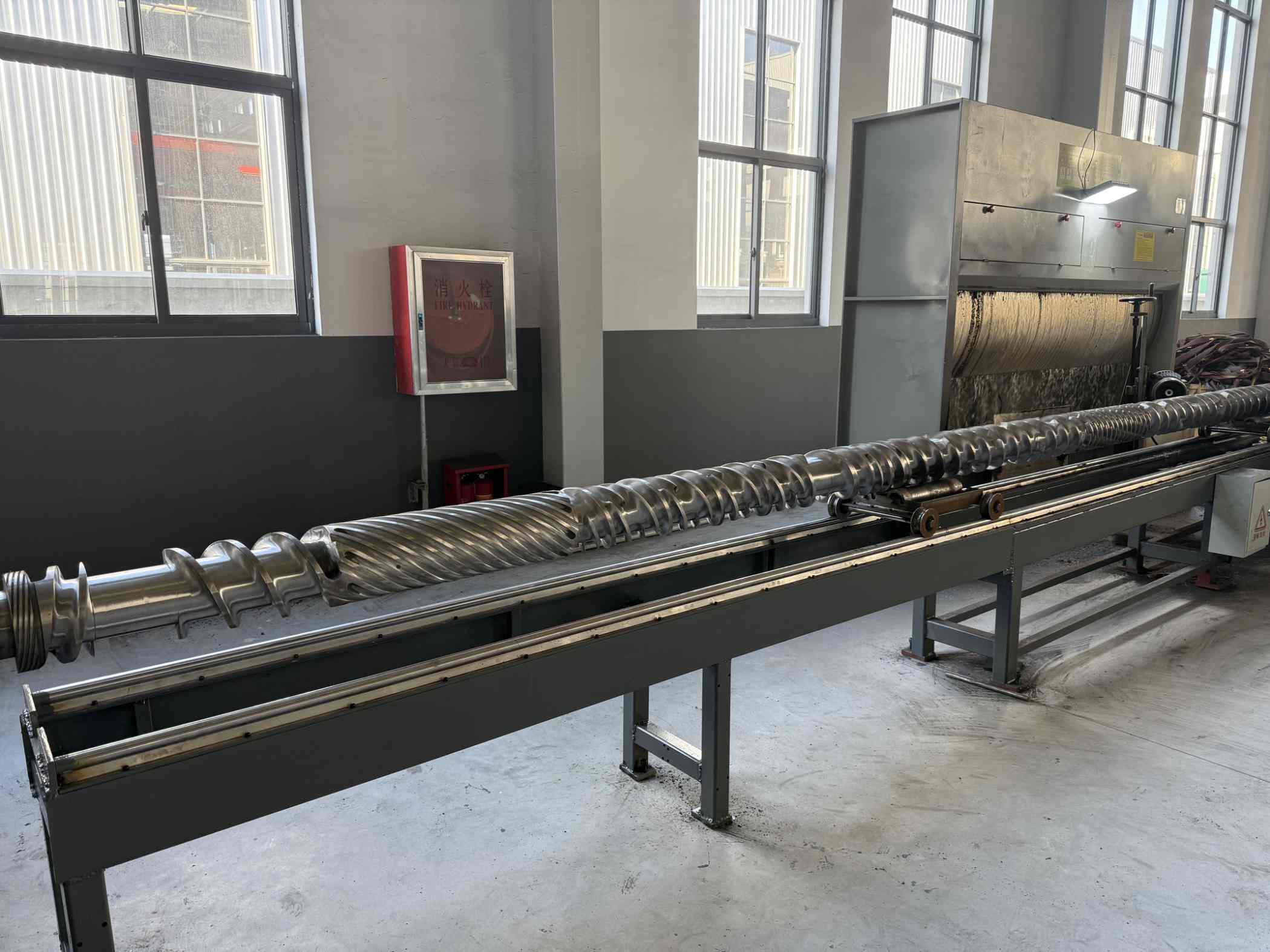
Map the screw from the feed end to the tip. Mark every crack, pit, peeled area, polished band, and discolored zone, with distance from a fixed point and the corresponding process section. This keeps a large defect from hiding smaller repeated damage.
Align the map with events such as a seized startup, idle heating, material change, aggressive purging, contamination, cooling interruption, or difficult removal. A local impact suggests a different mechanism from repeated circumferential damage. Damage where material first melts may also differ from damage near the metering end.
Why Nitrided Screw Surface Layers Fail
Separate Compound-Layer Fracture From Deeper Diffusion-Zone Damage
Nitriding forms a hard surface region supported by a deeper diffusion zone. The outer compound layer can be more brittle, so it may chip or craze without proving the entire case has failed. A continuous-looking surface can still have reduced effective case depth after wear or refinishing.
Thin flaking calls for microscopy and contamination control, while a deep crack requires substrate evaluation. Do not call every missing patch “case depth loss.” Reserve that term for a measured reduction in hardened depth, not an inference from color or texture.
Test Abrasion, Corrosion, Overload, Thermal Cycling, and Cleaning Damage Against the Evidence
Test competing causes instead of choosing the most familiar one. Abrasion tends to produce directional scoring and diameter loss. Corrosion may create pits or undercut areas where aggressive additives or residue were present. Overload can leave deformation, drive alarms, or cracks near abrupt geometry changes.
Thermal cycling becomes more credible when damage follows repeated heating and cooling interruptions. Cleaning damage should be considered when sharp tools, uncontrolled blasting, or forceful removal contacted the surface. The strongest diagnosis explains the damage shape, its location, and the operating timeline at the same time. If one explanation fits only the appearance, keep investigating.
How to Inspect Cracking, Peeling, and Case-Layer Loss
Begin With Controlled Surface Preparation, Visual Mapping, and Dimensional Checks
Stop safely, preserve loose particles, and photograph the screw before cleaning. Remove polymer without cutting, grinding, or rounding the metal. Inspect under consistent lighting and magnification. A compatible nondestructive method applied by qualified personnel may help reveal surface-breaking cracks.
Measure screw diameter and flight dimensions at repeatable axial positions and compare them with original records when available. The site’s guide to measuring screw and barrel wear tolerances provides a useful framework for keeping these readings position-specific. A single diameter value cannot show whether wear is localized or whether clearance changes along the plasticizing section.
Confirm Hardness Profile and Effective Case Depth Through Laboratory Testing
When repair or replacement depends on the remaining case, laboratory work is necessary. A representative cross-section can show the compound layer, diffusion zone, crack path, and the transition into the substrate. A hardness traverse from the surface inward helps determine effective case depth and whether the support beneath the surface remains consistent.
Sampling is destructive, so choose the location around the failure pattern and service decision. Portable hardness readings may support screening but do not replace a depth profile. The laboratory should document preparation, indentation locations, microstructure, and its effective-case-depth definition.
Separate Surface Failure From General Screw and Barrel Wear
Compare Screw Diameter, Flight Condition, Barrel Bore, and Clearance by Position
A screw does not wear in isolation. Measure the barrel bore at corresponding positions and calculate working clearance rather than judging either component separately. A worn bore can increase leakage and allow screw movement even when the screw’s surface damage looks limited. An intact bore with sharply localized screw damage points the investigation elsewhere.
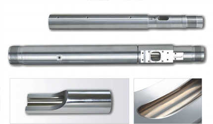
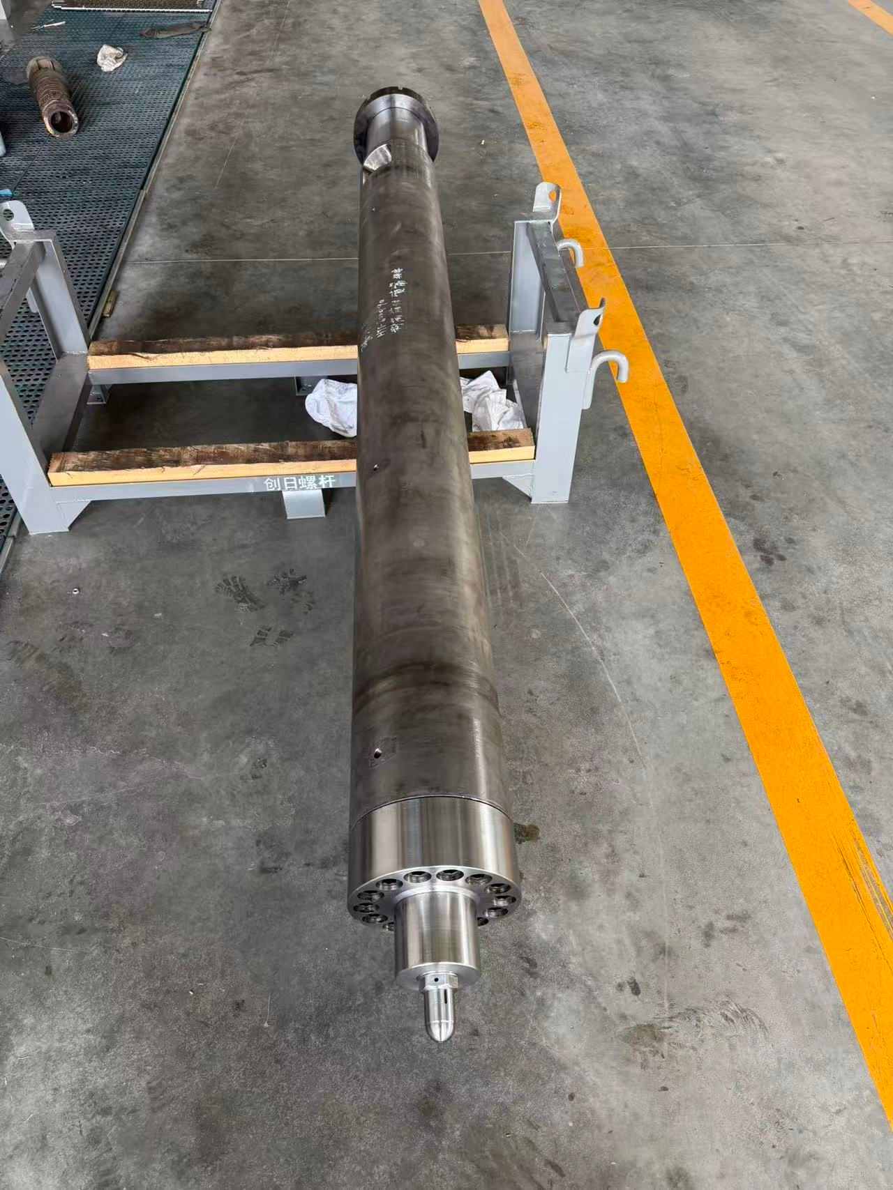
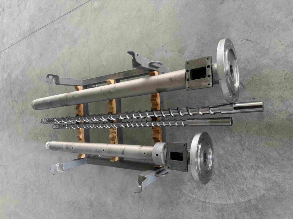
For injection applications, the Injection Molding Barrel is the matching surface against which screw measurements must be interpreted. At CHUANGRI SCREW, we use position-based screw and barrel information to support a more focused manufacturing or replacement review instead of treating every surface mark as the same failure.
Relate Melt Quality, Pressure Instability, and Output Changes to the Damage Pattern
Process symptoms rank findings but are not proof. Falling output, longer recovery, pressure fluctuation, black specks, or inconsistent melt may also come from heaters, controls, material, nonreturn components, or barrel wear. Match symptom timing to mapped damage and measured clearance.
Material contamination raises urgency. Save representative pellets, purge material, or molded parts and note when particles first appeared. If metallic fragments correspond to a peeling region, continued production can spread damage and contaminate downstream equipment. If no surface particles are found, retain the evidence anyway; absence of debris does not make a crack safe.
Decide When the Nitrided Screw Must Leave Service
Define Stop-Use Triggers for Deep Cracks, Active Peeling, and Material Contamination
Remove the screw from service when a crack appears deep, grows, crosses a critical transition, or accompanies deformation. Active peeling, repeated metal particles, fast dimensional change, or contact marks indicating unstable clearance are also stop-use conditions.
Do not grind away a defect simply to improve its appearance. That can erase evidence, change dimensions, and remove more of the hardened case. Quarantine the part, label its orientation, retain loose fragments, and protect the surface from corrosion before expert review.
Build the Evidence Needed for Re-Nitriding, Repair, or Replacement Review
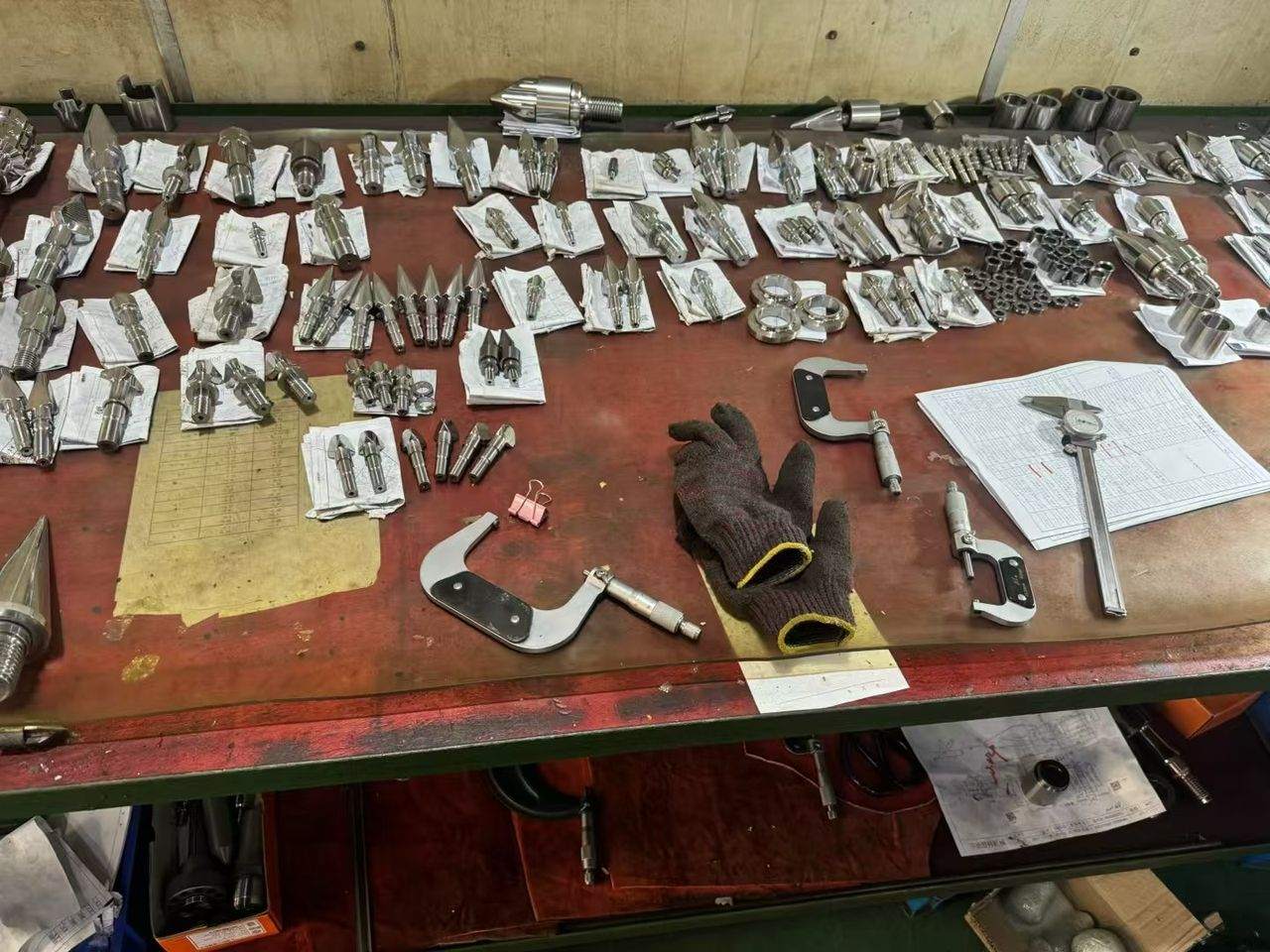
A useful review package includes the damage map, photographs, position-based dimensions, barrel bore data, materials, temperatures, loads, alarms, cleaning history, and prior repairs. Add laboratory findings when cracking or case depth loss affects the decision. This separates a surface-treatment question from a geometry or substrate problem.
Re-nitriding is not an automatic answer to any worn nitrided screw. The part must first have suitable dimensions, crack-free material, and enough machining allowance for the proposed route. Repair feasibility depends on where material would be removed or added and how final geometry will be restored. Replacement becomes the clearer option when structural integrity, dimensional recovery, or contamination control cannot be demonstrated.
FAQ
Q: What are the first signs of nitrided screw surface failure?
A: Warning signs include sharp-edged flakes, branching or continuous cracks, rough patches that shed particles, localized pitting, and fast changes in diameter or clearance. Smooth polishing or discoloration alone is not enough to confirm failure.
Q: Can a nitrided screw keep running after the layer starts peeling?
A: Continued use is risky when peeling is active because fragments can contaminate material and the exposed area may wear faster. Stop the machine, preserve evidence, and assess crack depth, dimensions, and barrel condition before deciding.
Q: How is case depth loss on a nitrided screw confirmed?
A: Effective case depth is confirmed through a prepared cross-section, microstructural examination, and a hardness traverse from the surface toward the substrate. Surface appearance or a portable hardness reading cannot establish the remaining depth alone.
Q: Does nitrided screw cracking always mean the screw must be replaced?
A: Not every superficial indication has the same severity, but a confirmed deep or growing crack is a serious structural concern. Repair or replacement should be decided from crack path, location, dimensions, substrate condition, and qualified technical review.
Q: What records should be collected for nitrided screw inspection?
A: Collect mapped defect locations, photographs before and after controlled cleaning, screw and barrel measurements by position, operating events, processed materials, alarms, maintenance history, loose particles, and any laboratory hardness or microscopy results.

 consult
 WHATSAPP
 leave message
 top
top