


Extruder Barrel Alignment: Top Methods to Stop Premature Wear
Extruder Barrel Alignment: Top Methods to Stop Premature Wear


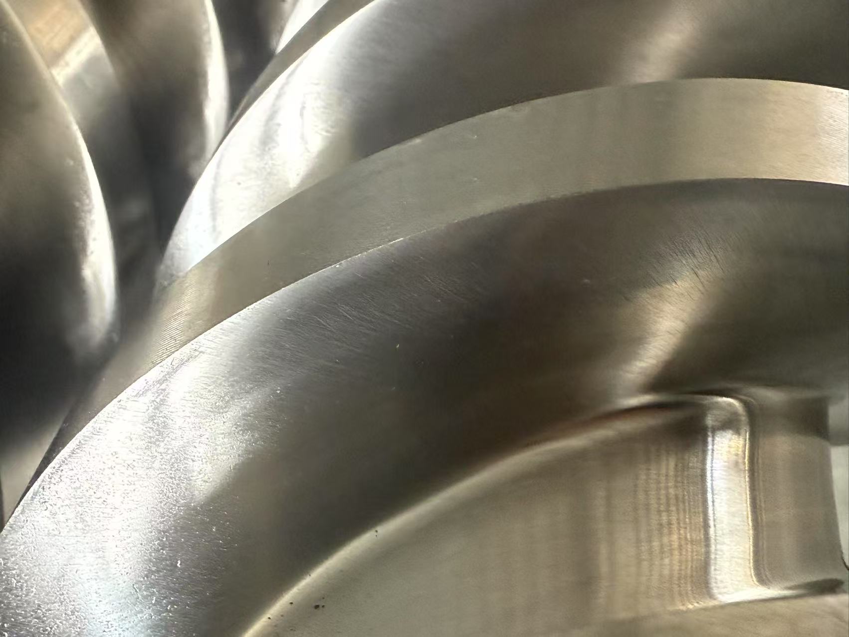
A polished flight edge shows where contact occurred. The mark alone leaves the cause open; inspect and measure it. Start an extruder barrel alignment review with that location. Output drift alone leaves too many explanations, including resin, fillers, temperature and operating settings. Put the wear observations beside the machine’s centerline measurements before ordering a repair. Follow the mark through the inspection record: its location, the matching geometry, and the remaining damage inform the repair decision.
What Does Extruder Barrel Alignment Have to Do with Premature Wear?
How can an offset centerline change screw-to-barrel clearance?
The specified clearance applies between a particular screw flight and its barrel bore. Record that pair of measurements together. With offset working axes, a generous gap on one side may accompany a tight gap opposite it. The tighter side can rub while material has more room on the other side. An end reading cannot describe that relationship throughout the barrel. Compare readings taken along the bore, keeping their orientation marked. Otherwise, a gap that changes direction between positions could disappear from the measurement record.
Why can uneven contact become a wear warning?
A polished area records contact; it does not record the reason for it. Scoring and localized flight or bore damage have the same limitation. Put their locations against the screw axis and barrel bore measurements, with the process record alongside. Vibration, contact noise, pressure instability or inconsistent output adds a reason to investigate, rather than a diagnosis. If an offset accounts for the marks, correcting it may prevent recurrence. Metal already lost remains a separate condition to assess.
How Can Operators Spot Misalignment Before Wear Accelerates?
What wear patterns should be compared around the barrel?
Mark the component’s orientation before removal; otherwise, ‘one side’ becomes difficult to relate back to the installed machine. Work along the flight edges and record where polishing, scoring or metal loss begins and ends. Then locate the corresponding marks inside the barrel. Record whether enlargement occupies one zone, forms a taper or gives different diameters when measured in different directions. Keep those observations separate. One isolated mark tells less than a pattern that can be traced between components.
Which operating changes deserve a closer inspection?
An operating log helps only if the conditions are comparable. Put the symptom beside the resin, screw speed, temperature profile, feed condition and die load recorded then. If output changed when the process changed, that difference needs investigating too. If metal-contact noise began after support work or a screw change, inspect what was disturbed. Changing several settings to recover output obscures this comparison. Retain the original readings and wear map before making adjustments to the machine.
Which Extruder Barrel Alignment Checks Help Protect the Screw?
How should supports, gearbox position, and mounting faces be checked?
Follow the machine reference through the connected drive, feed section, barrel and supports. At a locating face, cleanliness leaves another check outstanding: damage. Likewise, tightened fasteners do not tell you whether the component occupies its intended position. Compare the supports rather than accepting a level frame as evidence of a shared axis. Keep the measurement state on the record. A cold reading and an approved operating-condition check address different thermal conditions, so use the equipment maker’s procedure for each.
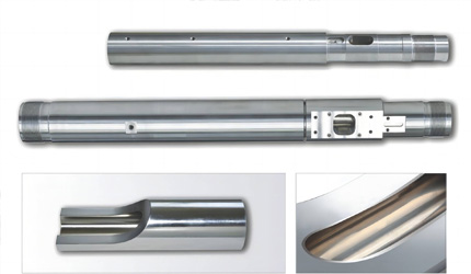
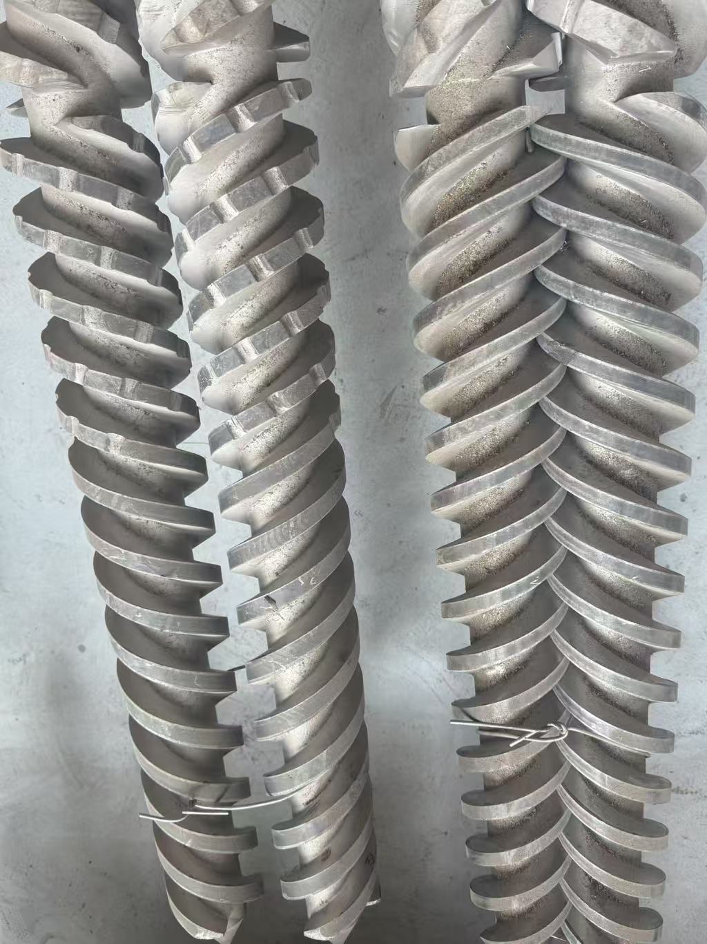
A parallel twin-screw barrel needs the same application review. Consider each screw and bore in its installed relationship, then check geometry, material, treatment and dimensions. The processing description leaves a question unanswered: does this specification suit the equipment being serviced? Put the application requirements beside it. Review geometry and treatment together at that stage; selecting a material first leaves the dimensions and fit still unresolved.
Where should centerline, runout, and clearance measurements be taken?
Use the axial position for each measurement entry. Under it, put barrel inside diameter, corresponding screw-flight outside diameter, and offset or runout direction. Keep the entries separate: an average would no longer show where a high spot, taper or oval bore was found. Include measurements beyond the accessible end and use calibrated equipment. At CHUANGRI SCREW, we examine screw-to-barrel fit and smooth rotation as well as fit clearance, concentricity, surface hardness and dimensional accuracy. We use coordinate-measuring equipment, bore gauges and hardness testers. Keep the readings with their acceptance reference: the machine drawing or approved engineering limit used for this assembly.
What Practices Keep Extruder Alignment Stable After Maintenance?
When should alignment be rechecked after service or a process change?
What did the maintenance work disturb? Trace the work back to the reference it could have changed: the moved machine, replaced or rebuilt screw, barrel, support or mounting arrangement. That identifies where checks need to resume under the equipment procedure, including safe isolation. After assembly, record whether rotation is smooth or whether contact or binding remains. Record the sequence and acceptance criteria taken from the machine procedure. Inspection sign-off needs those results before production resumes; appearance alone leaves the fit unconfirmed.
For replacement work, compare the screw and barrel product range with the machine data while planning installation. Once assembled, the selected components still need their fit and rotation checks.
How can consistent records reveal a developing alignment issue?
A measurement without a location is difficult to repeat. Attach orientation, instrument, date and operating state to the position on the record. Include the symptom that brought the component in for inspection. Someone repeating the check needs those details to make a comparison; changed points or methods leave the trend uncertain. Dimensions alone also leave repair questions unanswered. At CHUANGRI SCREW, dimensions are one part of our repair assessment. Material condition and structural integrity are assessed alongside the mating barrel and operating conditions. For plastic-machinery components, we offer worn-screw refurbishment, on-site measurement, design, modification and customization. Which work suits a damaged part depends on the findings.
How Should Wear Measurements Guide Repair or Replacement?
How can alignment-related wear be separated from other causes?
Put the contact marks against the offset measurements. A mismatch leaves the adjustment without a demonstrated link to the symptom. An enlarged bore needs attention in its own right: moving it cannot put worn metal back. Review what passed through the machine and how it ran, including resin and filler exposure, temperature history and process changes. Check for abrasion, corrosion, a bent screw and damaged supports too. For wear protection, record resin, glass or mineral fillers, corrosive exposure and temperature beside the wear location and mechanism. Examine the steel beneath the affected zone before choosing a surface layer. Any substrate cracking, corrosion or structural damage must be resolved, even where a new layer could hide it.
What evidence should be reviewed before choosing a repair?
Before approving work, put the dimensional map beside the surface and material assessment. List what adjustment would correct and what damage would remain afterward. A rebuilt flight or coating cannot stand in for that assessment. Our worn-screw refurbishment, measurement and design work at CHUANGRI SCREW depends on the condition of the screw and its mating barrel. For a replacement, put the machine data beside the bimetallic barrel configuration and review suitability for the application. The material label leaves fit unresolved.
FAQ
Q: Can extruder barrel misalignment cause premature wear?
A: Yes, where an offset produces uneven contact. Map the one-sided wear against the clearance, straightness and bore measurements. A pattern, reviewed with process records, helps distinguish alignment from other causes.
Q: How do I check extruder barrel alignment?
A: Begin with the machine maker’s procedure and its intended screw axis. Record barrel position and clearance at repeatable locations along the working length. Use machine-specific acceptance limits.
Q: What are the signs of extruder screw and barrel misalignment?
A: Investigate one-sided flight polishing or scoring and localized bore marks. Include vibration, metal-contact noise, unstable pressure and inconsistent output in records. None proves misalignment alone.
Q: How often should extruder barrel alignment be checked?
A: The maintenance schedule from the machine maker provides the interval. Work on the drive, supports, screw, barrel or mounting references calls for another check. New wear or operating symptoms warrant investigation promptly.
Q: Can a worn extruder barrel be repaired after alignment problems?
A: The condition assessment precedes work. Compare measured dimensions with the material condition and structural integrity, including the mating screw in the review. Operating conditions matter too. Decide what is repairable before selecting work.

 consult
 WHATSAPP
 leave message
 top