How to Align an Extruder Screw and Barrel: A Complete Guide to Improve Performance and Reduce Wear
Related news
How to Align an Extruder Screw and Barrel: A Complete Guide to Improve Performance and Reduce Wear


Many extrusion issues originate from installation deviations rather than poor screw design. To achieve proper extruder alignment, establish the positional relationship between the gearbox, feed section, barrel, supports, and screw before minor errors develop into contact, heat buildup, pressure fluctuations, or wear. Proper screw and barrel alignment helps minimize friction, maintain consistent screw clearance, stabilize output, and extend component service life. The alignment process should be based on measured centerlines and actual component conditions, not simply machine level. This guide provides a practical procedure for checking alignment, adjusting barrel position, and verifying smooth screw rotation without contact.
Why You Need to Properly Align an Extruder Screw and Barrel
Correct alignment ensures that the screw flight remains centered within the barrel bore throughout the working length. It is a critical mechanical condition that protects component fit, process consistency, and long-term equipment reliability.
How Misalignment Affects Extruder Performance
Misalignment causes uneven screw contact and increases friction along one side of the barrel. This can raise drive load and energy consumption, while localized heat changes may affect polymer processing conditions. As the conveying clearance becomes inconsistent, melt pressure stability can decrease and effective output may be reduced.
The resulting damage develops over time: one side of the screw flight may experience accelerated wear, while the barrel bore can develop scratches, uneven wear, or localized enlargement.
Common Signs Your Extruder Needs Alignment Checking
Check alignment when you observe:
*Unusual vibration under otherwise comparable conditions
* Metal contact noise during rotation or start-up
* Uneven screw-flight wear or one-sided polishing
* Unstable extrusion pressure or inconsistent output
* Shorter screw life with similar resin and settings
These signs do not prove misalignment alone. Review them with clearance, straightness, bore condition, and process data.
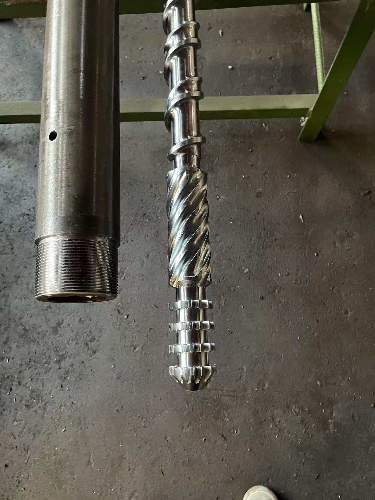
What Causes Extruder Alignment Problems?
Alignment problems usually come from errors across the drive, mounting, and thermal system.
Incorrect Barrel Installation and Positioning
Contaminated mounting surfaces, uneven supports, damaged shims, incorrect spacers, or premature tightening can shift the barrel centerline. Clean and inspect flanges, locating faces, bolts, and supports. Do not force the barrel into position by tightening one side first.
Gearbox, Feed Section, and Barrel Centerline Errors
The alignment reference should come from the drive system and actual screw axis. “Machine level equals alignment” is not a valid conclusion. Check the gearbox output, feed throat, barrel bore, and screw as related centerlines. For replacement work, confirm machine data, dimensions, and mounting references.
Thermal Expansion and Operating Conditions
Heating can cause barrel expansion, support movement, and changes in screw and barrel clearance. Cooling channels, temperature zones, feed-throat conditions, and die loading can alter the operating relationship. Compare cold measurements with the approved procedure, and use qualified personnel for any controlled hot-condition review.
How to Align an Extruder: Step-by-Step Procedure
Acceptance depends on the machine drawing, screw design, barrel construction, and manufacturer’s requirements. Use the following inspection framework.
Prepare Alignment Tools and Inspect Components
Prepare a dial indicator, laser alignment equipment where appropriate, bore gauge, straightedge, measuring tools, cleaning materials, and specified shims or supports. Isolate electrical, hydraulic, pneumatic, and thermal energy before removing guards, and confirm a safe temperature.
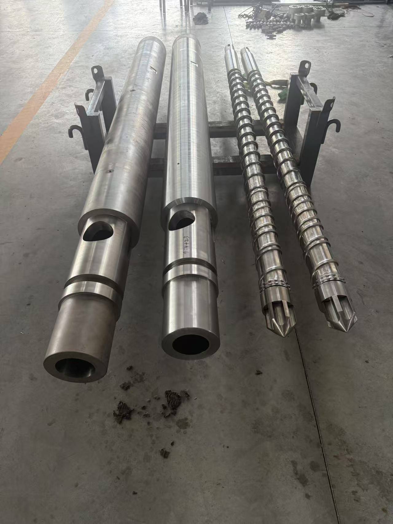
Inspect screw straightness, shaft and flight condition, barrel bore, flanges, locating features, mounting surfaces, and support hardware. A bent screw, damaged bore, cracked base, or severe wear needs engineering evaluation first.
Check the Extruder Centerline Before Adjustment
Work from the drive side toward the die:
1.Check the gearbox reference and intended screw axis.
2. Verify feed-section and barrel position against that axis.
3. Measure vertical and horizontal deviation at repeatable points.
4. Compare the barrel bore with the screw axis using a bore gauge or equivalent method.
5. Where wear is suspected, compare barrel ID and screw-flight OD at matching axial locations.
Record the direction and magnitude of deviation. Local enlargement, ovality, taper, or one-sided wear can be missed by a single average reading.
Adjust Barrel Position and Confirm Screw Clearance
Make controlled changes to the vertical position, horizontal position, and support points. Recheck the centerline after each adjustment because changing one support can move another reference. Tighten fasteners in a sequence that preserves the measured position.
Then install or rotate the screw according to the equipment procedure. Confirm smooth movement through the accessible rotation range without metal contact, binding, or abnormal resistance. Use the machine drawing or approved engineering standard instead of a generic clearance value.
At CHUANGRI SCREW, we consider clearance, concentricity, and dimensional accuracy in production inspection. For maintenance, measure the relationship, document the result, and confirm free rotation before production.
How Proper Alignment Extends Screw and Barrel Service Life
Prevent Uneven Wear on Screw Flights and Barrel Bore
An off-center screw can force one flight edge to carry more rubbing and contact. Alignment helps reduce one-side wear, scratching, local heat, and excessive clearance. It also makes later wear measurements more useful.
If clearance has increased, inspect the geometry before choosing repair or replacement. Enlarged barrel ID, reduced flight OD, surface damage, or screw bending can require different decisions. A coating should not hide cracks, corrosion, or structural damage.
Improve Melt Quality and Production Stability
A centered screw supports more consistent conveying and plasticizing conditions. Better symmetry can help stabilize melt pressure and output, although resin, temperature, die resistance, geometry, and settings remain important.
Application matching matters too. CHUANGRI SCREW provides designs for pipe extrusion, including PE HDPE Pipe Extruder High-Speed Screw. Each application still requires machine data, material information, and fit review.
How Manufacturing Precision Helps Maintain Extruder Alignment
Alignment begins during manufacturing. Geometrically inconsistent components are harder to assemble and may wear faster.
CNC Machining and Surface Finishing Improve Fit Accuracy
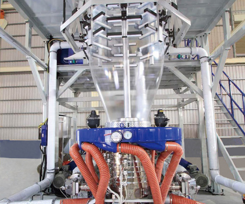
CNC turning establishes base dimensions, while thread milling forms the screw profile according to pitch, lead, and depth. Feeding, compression, metering, and mixing sections must remain consistent with the intended design. On the barrel side, bore honing and precision grinding affect bore accuracy and surface condition. For blown-film lines, see the High-Speed Blown Film Screw.
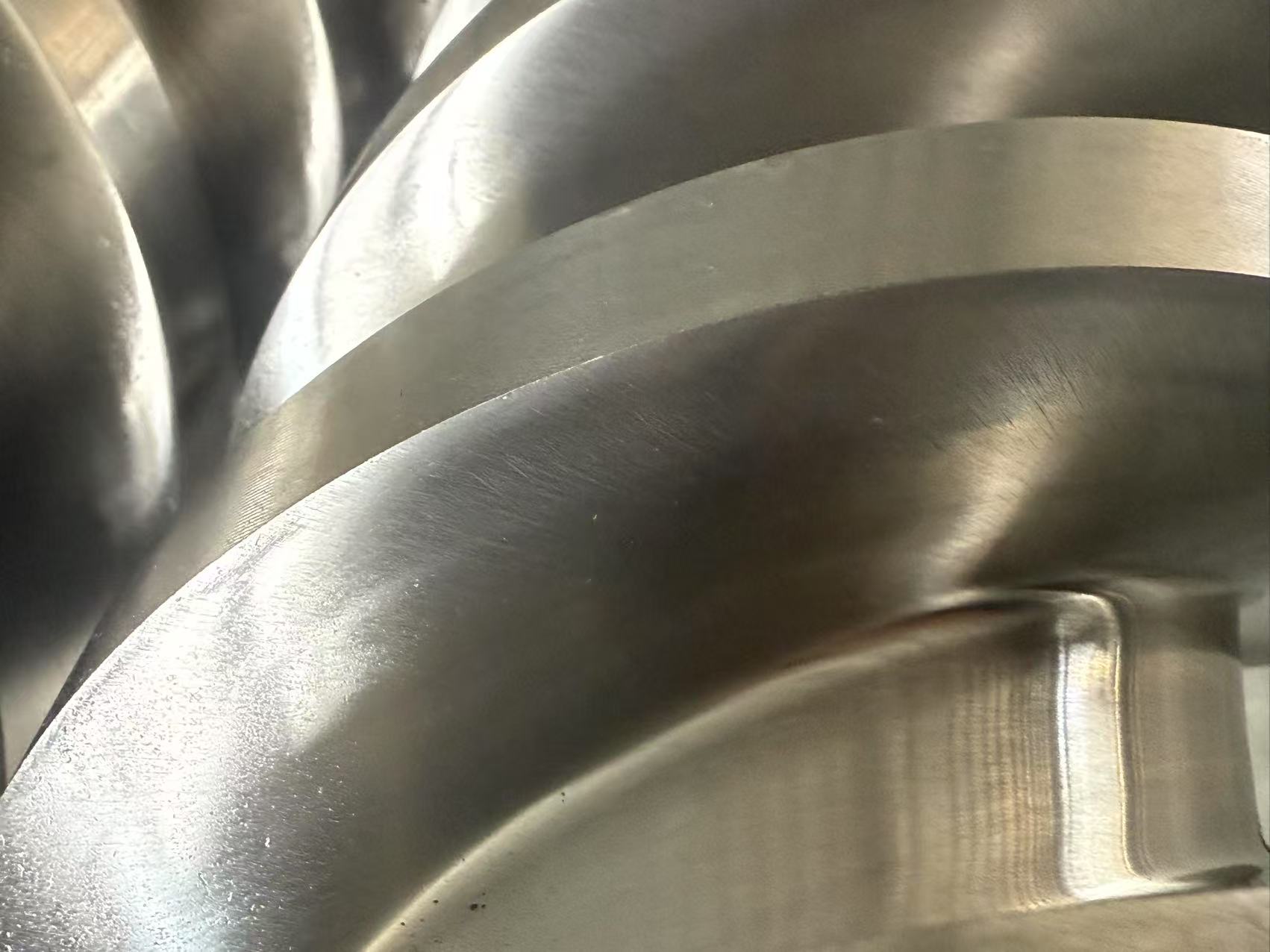
Grinding and polishing can remove machining irregularities and prepare surfaces for treatment. Acceptance depends on required clearance and concentricity, correct mating, and smooth rotation after processing.
Material Selection and Wear Protection Support Long-Term Alignment
Material and treatment should follow the resin, glass fiber or mineral filler, corrosion exposure, temperature, wear location, and wear mechanism. Options may include nitriding, bimetallic processing, quenching, alloy coating, grinding, and polishing. The documented nitriding process can reach surface hardness of HV900 or above; this is a capability reference, not a universal requirement.
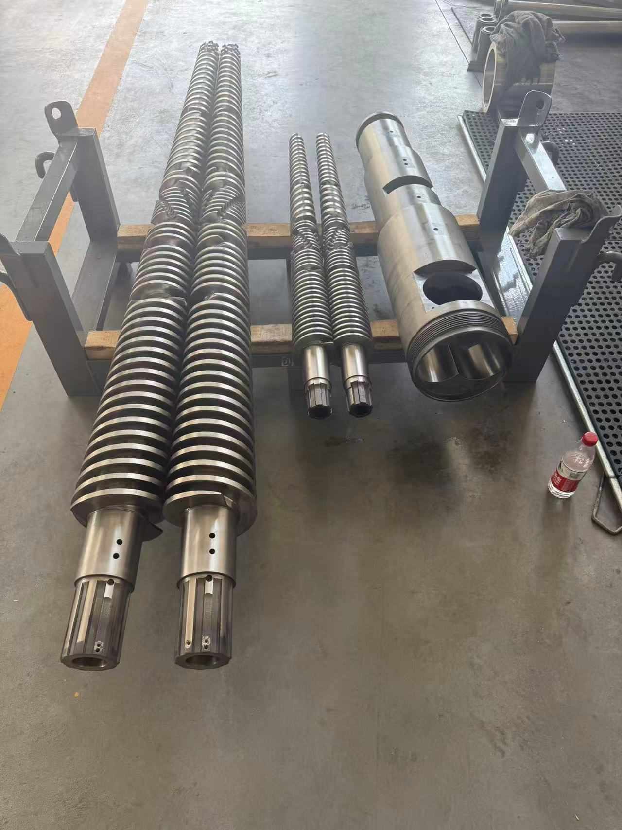
For moderate wear, nitriding may be considered. Stronger abrasive wear or combined abrasive-corrosive conditions may require a bimetallic or alloy solution. CHUANGRI SCREW uses coordinate-measuring equipment, internal-diameter gauges, and hardness testers to inspect fit clearance, concentricity, surface hardness, and dimensional accuracy. For pelletizing applications, review the Pelletizing Parallel Twin-Screw.
FAQ
Q: How often should you align an extruder?
A: Check it during installation, after moving or rebuilding the machine, after screw or barrel replacement, and when vibration, contact noise, uneven wear, or unstable pressure appears.
Q: How do you align an extruder screw and barrel correctly?
A: Establish the screw axis from the gearbox, measure barrel deviation, adjust supports and mounting position, then verify clearance and smooth rotation against the machine standard.
Q: What tools are needed to align an extruder?
A: Typical tools include a dial indicator, laser alignment equipment, bore gauge, straightedge, precision measuring tools, cleaning materials, and controlled shims or supports.
Q: Can you align an extruder without removing the screw?
A: Preliminary centerline and accessible clearance checks may be possible with the screw installed. A complete straightness, flight-wear, and bore inspection may require removal.
Q: How does misalignment affect an extruder screw and barrel?
A: It can cause uneven contact, friction, local heat, unstable pressure, higher energy use, one-sided flight wear, barrel-bore damage, and reduced output.

 consult
 WHATSAPP
 leave message
 top
top