
What Information Does a Feed Screw Manufacturer Need for a Custom Screw Design?
Related news
What Information Does a Feed Screw Manufacturer Need for a Custom Screw Design?


A custom feed screw is designed around a machine, a material, and a measurable production objective. A drawing is useful, but it describes what existed; it may not explain what the new screw must improve. The strongest RFQ combines geometry, operating data, material information, and evidence of the current problem.
What Should You Send a Feed Screw Manufacturer First?
Start with a drawing, specification, or physical sample
Send an approved drawing whenever one exists. It should identify nominal screw diameter, overall and working length, flighted length, drive-end geometry, keyway or spline, tip connection, and critical tolerances. Include the revision and clarify which dimensions are fixed.
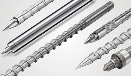
When no drawing is available, an existing screw sample can establish the geometry. A manufacturer can inspect flight dimensions, the drive interface, surface treatment, and wear locations. A worn sample is evidence of the installed condition, however, not an instruction to copy every worn dimension. Ask for a design review that separates original intent from wear loss.
Add the machine and application identity
Provide the machine manufacturer and model, process type, screw diameter, installed length, rotation direction, drive connection, spline or keyway, tip connection, and barrel identity. These interfaces determine what must remain fixed before a feed screw manufacturer can change conveying or melting geometry.
If the drawing or sample is incomplete, machine and application data still let engineers define the next measurement. Include the existing barrel, the resin family, the feed form, the target output, and the reason for replacement. This makes a partial RFQ useful instead of making missing documentation a dead end.
What Machine and Existing Screw Data Does a Feed Screw Manufacturer Need?
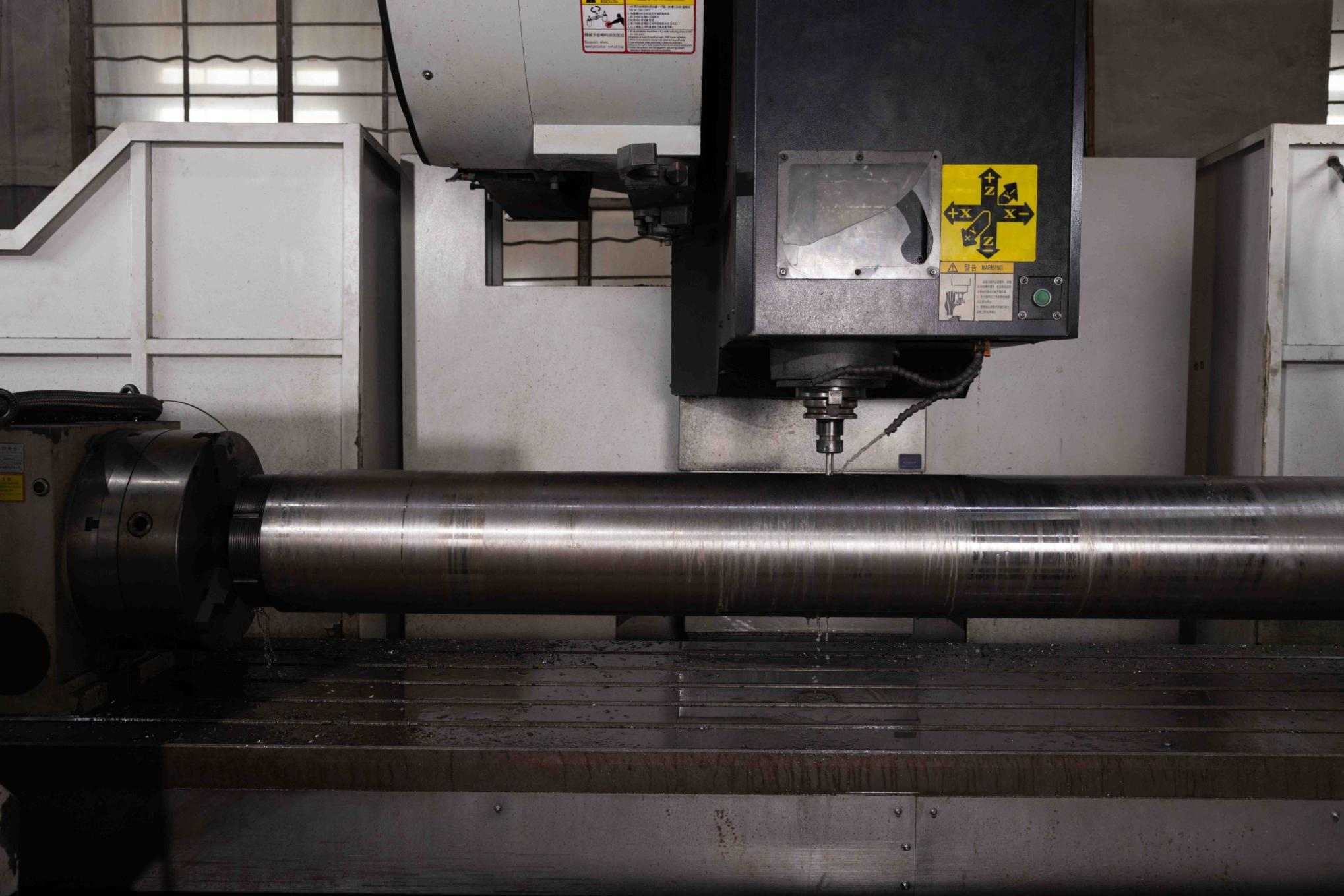
Match the screw to the barrel, not to a catalogue dimension
Report barrel bore ID, screw flight OD, known screw-to-barrel clearance, barrel condition, and any measured taper, ovality, or local enlargement. Barrel wear increases bore ID; screw wear reduces flight OD. Either change increases diametrical clearance. Measurements should be taken at matching axial positions and compared with the original drawing or an accepted baseline.
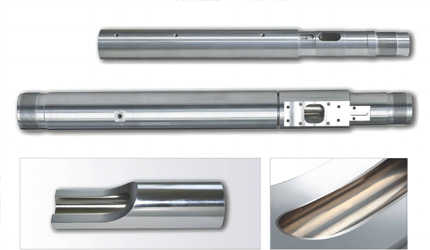
This distinction matters when a replacement screw is being considered. A new screw inside a worn barrel may not restore the intended working clearance. CHUANGRI SCREW documents barrel bore honing and precision grinding, with checks for fit clearance, concentricity, surface hardness, and dimensional accuracy. See our injection molding barrel manufacturing and inspection page when the barrel condition is part of the RFQ.
Separate fixed interfaces from redesign variables
Drive-end geometry, installed length, barrel fit, and tip connection are normally fixed machine interfaces. Feed depth, pitch, compression profile, transition length, metering depth, barrier structure, and mixing elements may be design variables. Do not approve a drawing that changes a fixed interface merely to solve a process symptom.
What Material and Process Information Should You Provide?
Identify the resin and the feed form
Give the polymer family and exact grade when available, MFR or MFI where relevant, normal processing temperature, thermal sensitivity, and whether one screw must run multiple resins. Then describe whether the feed is pellet, powder, flake, regrind, film scrap, or a blend. Include bulk-density variation, moisture, bridging, starvation, particle-size variation, and recycled content.
The same polymer in pellets and low-density film does not create the same solids-conveying requirement. CHUANGRI SCREW’s recycling knowledge distinguishes hard recycled material from soft PP/PE film and woven-bag feed, with side-feeding options used in suitable applications. Our recycling pelletizing screw and barrel range illustrates why feed form belongs in the design brief, not in a last-minute note.
Quantify fillers and additives
State glass-fiber, calcium-carbonate, mineral-filler, pigment, flame-retardant, processing-aid, and PCR percentages. Also identify corrosive ingredients and any recent formulation change. These details affect conveying, shear, mixing, heat generation, and wear protection, not only the base material selection.
Provide a real operating window
Send low, normal, and maximum conditions rather than one ideal setting. A useful process table includes:
|
Data to provide |
Why a feed screw manufacturer needs it |
|
Output at each condition |
Evaluates conveying capacity and specific output |
|
Screw RPM |
Shows the output-to-speed relationship |
|
Motor load or torque |
Shows available drive margin |
|
Melt or head pressure |
Indicates pumping and restriction demand |
|
Actual melt temperature |
Helps distinguish shear heating from barrel setpoints |
|
Barrel temperature profile |
Defines the current thermal environment |
|
Screen, die, and downstream limits |
Prevents assigning a downstream bottleneck to screw geometry |
Also record startup or upset conditions when they cause the failure. A custom screw must operate across a processing window, not only at a single favourable point.
What Existing Screw Problems Should You Show?
Describe the problem before proposing the remedy
Write what happens, when it happens, with which material, at what RPM and output, and whether it is continuous or intermittent. Useful examples include output surging, poor melting, high melt temperature, unstable pressure, gels, black specks, slow recovery, and premature wear. Link the change to a material lot, speed increase, extended run, startup, or maintenance event.
Avoid “need better performance” as the only requirement. State whether output, melt temperature, mixing, pressure stability, dispersion, recovery time, or defect rate is the primary constraint. This lets the feed screw manufacturer select a design direction that can be tested.
Send location-specific wear evidence
Provide photographs and measurements for the feed zone, compression zone, metering zone, mixing section, flight OD, root surface, coating loss, scoring, and corrosion. Add operating history and the measurement method. Local rounded flights or concentrated scoring can be more informative than an assumption that the whole screw wore evenly.
Exclude other causes before redesigning the screw
A worn barrel, hopper bridging, blocked screen, excessive die restriction, sensor drift, or downstream capacity limit can mimic a screw problem. A new screw alone may not restore clearance in a worn barrel. Confirm the machine-side evidence before turning a symptom into a redesign specification.
How Does a Feed Screw Manufacturer Turn Your Information into a Custom Design?
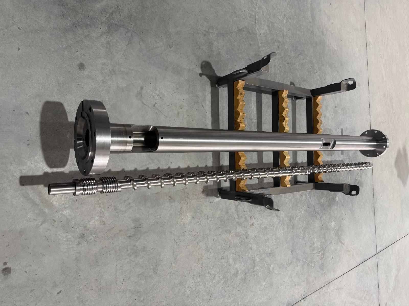
Convert data into design decisions
Feed form, bulk behaviour, and throughput target guide solids conveying, feed-zone volume, pitch, and flight strategy. Resin melting behaviour, viscosity, output, and melt-temperature target guide compression, metering, and mixing decisions. The article brief should explain the objective, while the manufacturer determines the dimensions after checking the machine limits.
Match wear protection and achievable performance
Wear and filler data determine protection. Moderate wear may justify nitriding; stronger abrasive exposure may call for a bimetallic system; combined corrosion and abrasion may require a nickel-based alloy system; severe abrasion may justify tungsten-carbide protection. CHUANGRI SCREW documents these options, but selection depends on the diagnosed mechanism and measured location. See our nitrided injection molding screw page for one verified product path.
Finally, test the target against motor power, torque, RPM, barrel condition, melt-temperature limits, screen and die restriction, and downstream capacity. A realistic design chain is: provided data, engineering constraints, screw geometry, material protection, and an achievable process target. That chain produces a better custom screw specification than a request for a fixed percentage increase.
FAQ
Q: What information should I send a feed screw manufacturer for a custom screw?
A: Send the drawing or sample, machine interfaces, barrel condition, resin and feed form, additives, operating window, product target, and location-specific problem or wear evidence.
Q: Can a feed screw manufacturer make a replacement screw without an original drawing?
A: Yes. A physical sample plus machine, barrel, material, and process data can establish the design basis. The worn dimensions should be treated as evidence, not automatically copied.
Q: Can a feed screw manufacturer copy a custom screw from an existing sample?
A: A sample can be inspected and reverse-engineered, but the manufacturer should separate original geometry from wear, damage, and previous design limitations before approving a replacement.
Q: Why does a feed screw manufacturer need resin, filler, and production data?
A: These inputs affect conveying, melting, shear, mixing, torque, pressure, temperature, and wear-protection choices. Without them, geometry cannot be tied to a defensible process objective.
Q: What measurements does a feed screw manufacturer need before designing a replacement screw?
A: Provide machine interfaces, installed length, barrel bore ID, flight OD, clearance at matching positions, process trends, and wear measurements by zone. There is no universal replacement dimension that fits every machine.

 consult
 WHATSAPP
 leave message
 top
top